


LoRa Spreading Factor Explained
Understanding LoRa/LoRaWAN data rates and spreading factors without a degree in electrical engineering.
If you’re working with LoRa/LoRaWAN you have heard about the spreading factor. This parameter significantly impacts the LoRa network, gateway throughput, and battery lifetime. Setting the spreading factor right is crucial for the whole network to work correctly and efficiently.
To understand the spreading factor we have to take a look at what a LoRa signal looks like.
Let’s start with the very basics.
Frequency and bandwidth
Frequency is the number of events (waves) transmitted per unit of time. The unit of frequency is hertz (Hz) which is equivalent to one event per second.
LoRa uses license-free radio bands; the frequency of channels differs according to the regional regulations. For example, in the EU, LoRa operates on mandatory channels of 868.10, 868.30, and 868.50 MHz with the fixed bandwidth of 125 kHz.
Bandwidth (BW) is the difference between the highest and the lowest frequencies of the signal.
For the channel of 868.10 MHz, chirps will be generated based on frequencies from 868.10 - BW/2 MHz to 868.10 + BW/2 MHz (ca 868.04 to 868.16 MHz).
Chirps
A chirp (also sweep signal) is a pulse in which the frequency either increases (up-chirp) or decreases (down-chirp) with time:
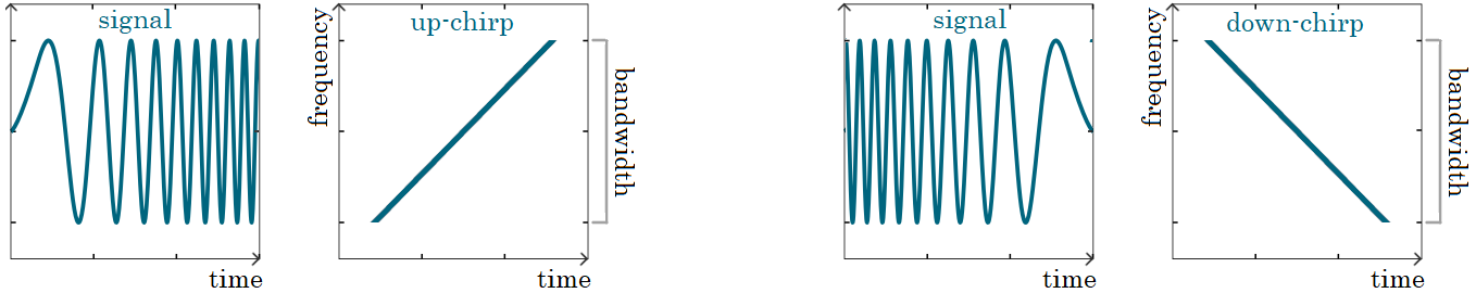
LoRa is a signal modulation based on Chirp Spread Spectrum (CSS). Linear frequency modulated chirps are carriers of information in the LoRa modulation.
There is some quite intimidating math behind the LoRa modulation. Luckily, for the purpose of this post we don't really need to delve any deeper into it.
Spreading factor and data rate
Spreading factor (SF) is the speed at which the signal frequency changes across the bandwidth of a channel.
Data rate (DR) is the number of bits that are processed per unit of time.
The spreading factor and data rate are obviously related: the higher the spreading factor the lower the data rate.
If the data is sent slowly the signal is easier to receive and distinguish from noise. On the other hand, sending data slowly means the data spends longer time on air and keeps the devices highly utilized which leads to bigger power (battery) consumption.
A higher data rate means a lower spreading factor and higher probability of packet loss.
We have to find a sweet spot in setting the spreading factor parameter for our requirements. Sure, the lower the spreading factor the more efficient our network, but it is not possible to use lower spreading factors everywhere.
Signal change with different spreading factors
Now, we have enough information to finally answer the interesting question:
How must the signal change for different spreading factors?
Let me answer this with a picture.
The following figure shows signals with two different spreading factors (SF0 and SF1). With the higher spreading factor (SF1) just one chirp is transmitted in the time unit. With the lower spreading factor (SF0) two chirps are transmitted in the same time unit:
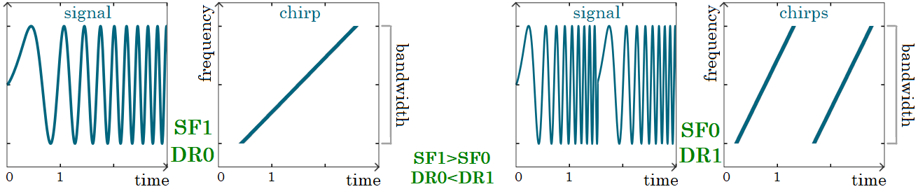
We can see that with the lower spreading factor (SF0) the frequency increases more rapidly (double the speed) and the chirps are steeper. Such a signal can transfer more data (its data rate is higher), however, is more error-prone as it is more difficult to distinguish it from noise.
Happy transmitting!